
Views: 66
Watch how to achieve a good perpetual fire in your models, screaming realism…!Paper model; Papercraft; Maquette en papier; Maquette en carton; comment faire; how to; diy; star wars; jeep willys; Les plus belles maquettes en papier; real size
Dare technology… I tried to be as complete as possible
The electronics and programmingPagode en papier carton; Les plus belles maquettes en papier; pagode Japonaise; japanese Pagoda; tie fighter, electronics led,command led; pic
The lighting of the Pagoda is provided by a PIC 12F1822(40) type microcontroller.
Two LEDs placed in the alcoves illuminate the Buddahs, their intensity can be adjusted using a small potentiometer. The microcontroller also manages the “fire” effect by means of three LEDs, two yellow and one red. The effect is obtained by an algorithm that produces intensity differences (by PWM). You can find the C program here.
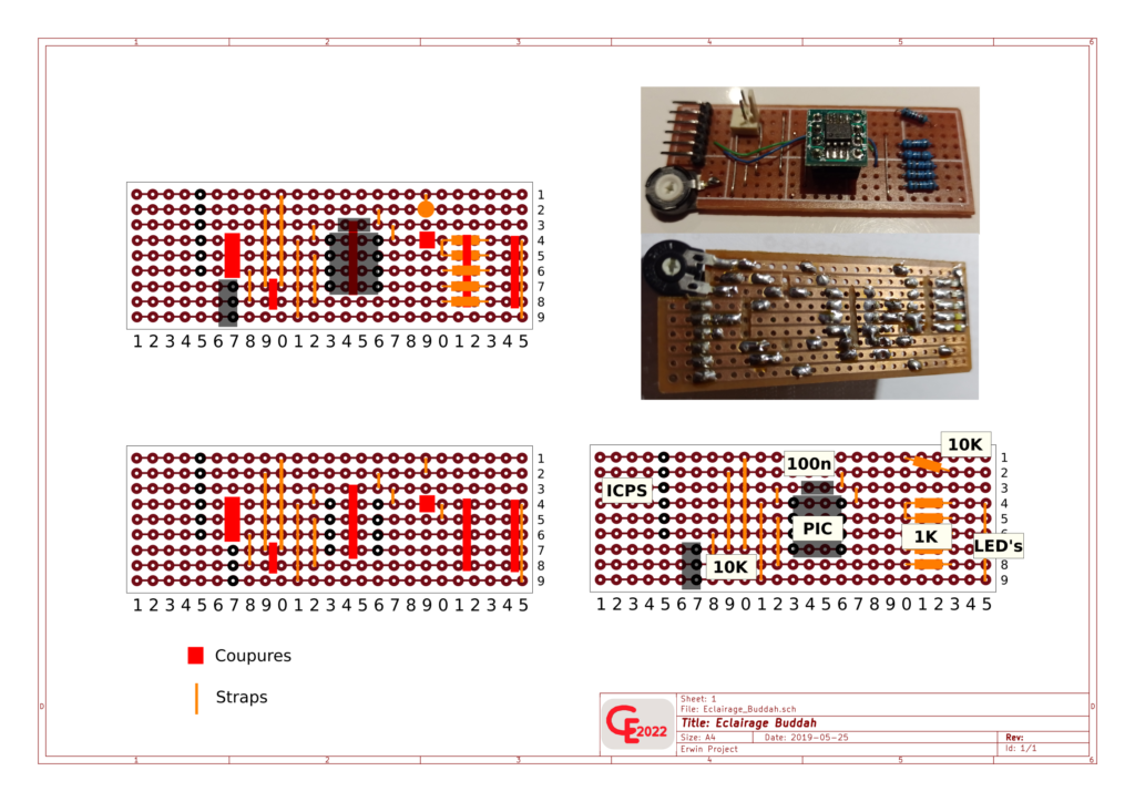
The control could be done from any µP, such as the Arduino, but the choice was made based on the space, indeed all the electronics fit on a plate barely larger than an Arduino nano. An example breadboard is attached to the documentation. A simple 5V power supply, USB charger style, is enough to power everything.Les plus belles maquettes en papier; pagode Japonaise; japanese Pagoda; tie fighter, electronics led,command led; pic
For detailed photos consult the page in French version
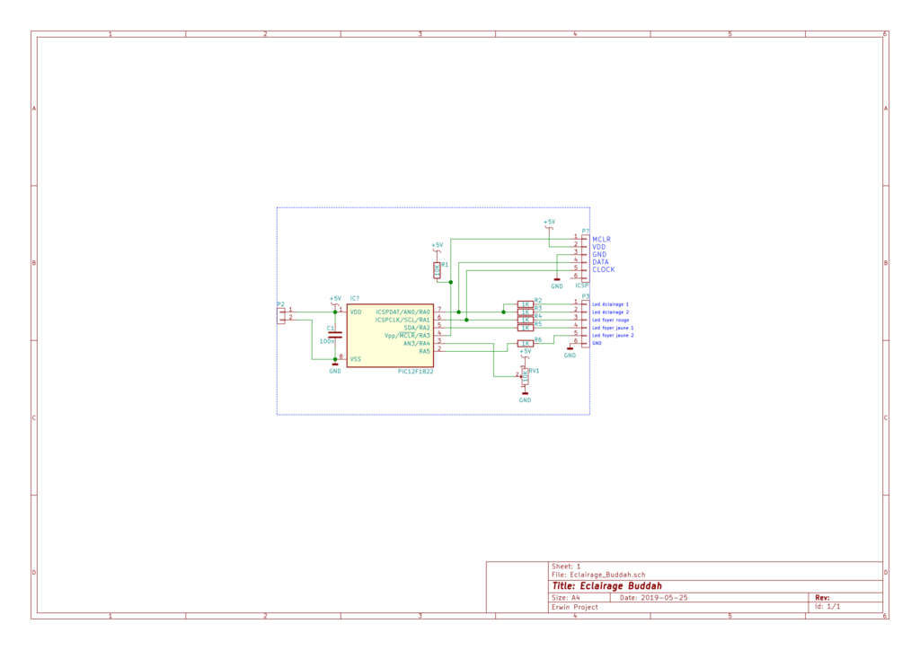
Schematic Diagram :
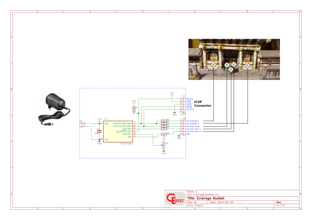
The Schematic :
The Print Board :
Video’s :
The Software… :
/*
* File: Feu_camp.c
* Author: Erwin
*
* Created on 20 mai 2019
*
*/
// PIC12F1822 Configuration Bit Settings
// ‘C’ source line config statements
// CONFIG1
#pragma config FOSC = INTOSC // Oscillator Selection
#pragma config WDTE = OFF // Watchdog Timer Enable
#pragma config PWRTE = OFF // Power-up Timer Enable
#pragma config MCLRE = OFF // MCLR Pin Function Select
#pragma config CP = OFF // Flash Program Memory Code Protection
#pragma config CPD = OFF // Data Memory Code Protection
#pragma config BOREN = ON // Brown-out Reset Enable
#pragma config CLKOUTEN = OFF // Clock Out Enable
#pragma config IESO = OFF // Internal/External Switchover
#pragma config FCMEN = ON // Fail-Safe Clock Monitor Enable
// CONFIG2
#pragma config WRT = OFF // Flash Memory Self-Write Protection
#pragma config PLLEN = ON // PLL Enable
#pragma config STVREN = ON // Stack Overflow/Underflow Reset Enable
#pragma config BORV = LO // Brown-out Reset Voltage Selection
#pragma config LVP = OFF // Low-Voltage Programming Disable
// #pragma config statements should precede project file includes.
// Use project enums instead of #define for ON and OFF.
#include <xc.h>
#include <stdio.h>
#include <stdlib.h>
#include <pic12F1840.h>
#define _XTAL_FREQ 32000000
//++++++++++++++++ Port output definitions
#define Led_red LATA1
#define Led_orange LATA2
#define Led_yellow LATA5
#define Led LATA0
//++++++++++++++++ Led variables
int Led_period = 270;
int Led_counter = 0;
char Led_duty = 150;
int temp_led = 0;
int Led_red_counter = 0;
char Led_red_duty = 0;
char temp_red;
char work_r = 0;
char time_pause_r = 1;
int Led_orange_counter = 0;
char Led_orange_duty = 0;
char temp_orange;
char work_o = 0;
char time_pause_o = 1;
int Led_yellow_counter = 0;
char Led_yellow_duty = 0;
char temp_yellow;
char work_y = 0;
char time_pause_y = 1;
char y,o,r = 0; //Duty random values
char a,b,c = 0; //Speed regulator counter
char z = 0; //Random delay counter
__bit sens_r; //0 = lightning up, 1 = lightning down
__bit pause_r; //speed of lightning
__bit sens_o;
__bit pause_o;
__bit sens_y;
__bit pause_y;
void init()
{
OSCCON = 0b11110000; //int osc = 8Mhz (+PLL on = 32Mhz)
ANSELA = 0b00001000; //AN3 on for pot
TRISA = 0b00011000; //AN3 = input
PORTA = 0x00;
ADCON0 = 0b00001100; //AN3 Selected
ADCON1 = 0b11000000; //Fosc/4, Vref = VDD
T2CON = 0b00000000; //TMR2 prescaler = 1:1, postscaler = 1:1
PR2 = 80; //32Mhz/4 = 125ns * 80 = 10uS (time base)
TMR2IE = 1; //TMR2 INT ON
PEIE = 1;
GIE = 1;
}
void main()
{
init();
temp_red = 200;
temp_orange = 180;
temp_yellow = 150;
TMR2ON = 1;
while(1)
{
//++++++++++ Calculate duty random values
y++;
if(y == 200) //Max illumination for Yellow led
{
y = 1;
}
o++;
if(o == 180)
{
o = 1;
}
r++;
if(r == 150)
{
r = 20;
}
for(z=0;z<(rand()%250);z++) //Random delay
{
__delay_us(330);
}
//+++++++++++ Get value of pot for Led illumination
ADON = 1;
__delay_ms(1);
GO_nDONE = 1;
while(GO_nDONE);
temp_led = ADRESH << 8;
temp_led = temp_led | ADRESL;
Led_duty = temp_led >> 2;
ADON = 0;
}
}
void __interrupt() ISR (void)
{
if(TMR2IF == 1)
{
PR2 = 80;
Led_counter++;
if(Led_counter >= Led_duty) //***********
{ // *
Led = 0; // *
} // ***************
if(Led_counter >= Led_period) //-Led_duty-
{ //variable (AN3 value)
Led = 1; //——–Led_period——-
Led_counter = 0; //fix for all leds
}
if(work_r == 0)
{
if(Led_red_duty == temp_red) //wait for full illumination
{ //to reverse way
sens_r = 1;
}
if(sens_r == 0) //lightning up
{
Led_red_duty++;
work_r = 1;
}
else if(sens_r == 1) //lightning down
{
Led_red_duty–;
work_r = 1;
if(Led_red_duty < 20)
{
Led_red_duty = 20; //Reset all
Led_red_counter = 0;
sens_r = 0;
temp_red = r; //New random duty value
time_pause_r = (r/100)+1; //New random speed value
}
}
}
if(work_o == 0)
{
if(Led_orange_duty == temp_orange)
{
sens_o = 1;
}
if(sens_o == 0)
{
Led_orange_duty++;
work_o = 1;
}
else if(sens_o == 1)
{
Led_orange_duty–;
work_o = 1;
if(Led_orange_duty < 1)
{
Led_orange_duty = 0;
Led_orange_counter = 0;
sens_o = 0;
temp_orange = o;
time_pause_o = (o/100)+1;
if(time_pause_o > 3)
{
time_pause_o = 2;
}
}
}
}
if(work_y == 0)
{
if(Led_yellow_duty == temp_yellow)
{
sens_y = 1;
}
if(sens_y == 0)
{
Led_yellow_duty++;
work_y = 1;
}
else if(sens_y == 1)
{
Led_yellow_duty–;
work_y = 1;
if(Led_yellow_duty < 1)
{
Led_yellow_duty = 0;
Led_yellow_counter = 0;
sens_y = 0;
temp_yellow = y;
time_pause_y = (y/100)+1;
if(time_pause_y > 3)
{
time_pause_y = 2;
}
}
}
}
if(work_r == 1)
{
Led_red_counter++;
if(Led_red_counter == Led_red_duty)
{
Led_red = 0;
}
if(Led_red_counter == Led_period)
{
Led_red_counter = 0;
Led_red = 1;
a++; //**
if(a == time_pause_r) //**
{ //**
work_r = 0; //** Speed regulator
a = 0; //**
} //**
}
}
if(work_o == 1)
{
Led_orange_counter++;
if(Led_orange_counter == Led_orange_duty)
{
Led_orange = 0;
}
if(Led_orange_counter == Led_period)
{
Led_orange_counter = 0;
Led_orange = 1;
b++;
if(b == time_pause_o)
{
work_o = 0;
b = 0;
}
}
}
if(work_y == 1)
{
Led_yellow_counter++;
if(Led_yellow_counter == Led_yellow_duty)
{
Led_yellow = 0;
}
if(Led_yellow_counter == Led_period)
{
Led_yellow_counter = 0;
Led_yellow = 1;
c++;
if(c == time_pause_y)
{
work_y = 0;
c = 0;
}
}
}
TMR2IF = 0;
}