
Views: 66
Regardez comment réussir un bon feu perpétuel dans vos maquettes, criant de réalisme…!Paper model; Papercraft; Maquette en papier; Maquette en carton; comment faire; how to; diy; star wars; jeep willys; Les plus belles maquettes en papier; real size
Osez la technologie… J’ai essayé d’être le plus complet possible
L’électronique et la programmation Pagode en papier carton; Les plus belles maquettes en papier; pagode Japonaise; japanese Pagoda; tie fighter, electronics led,command led; pic
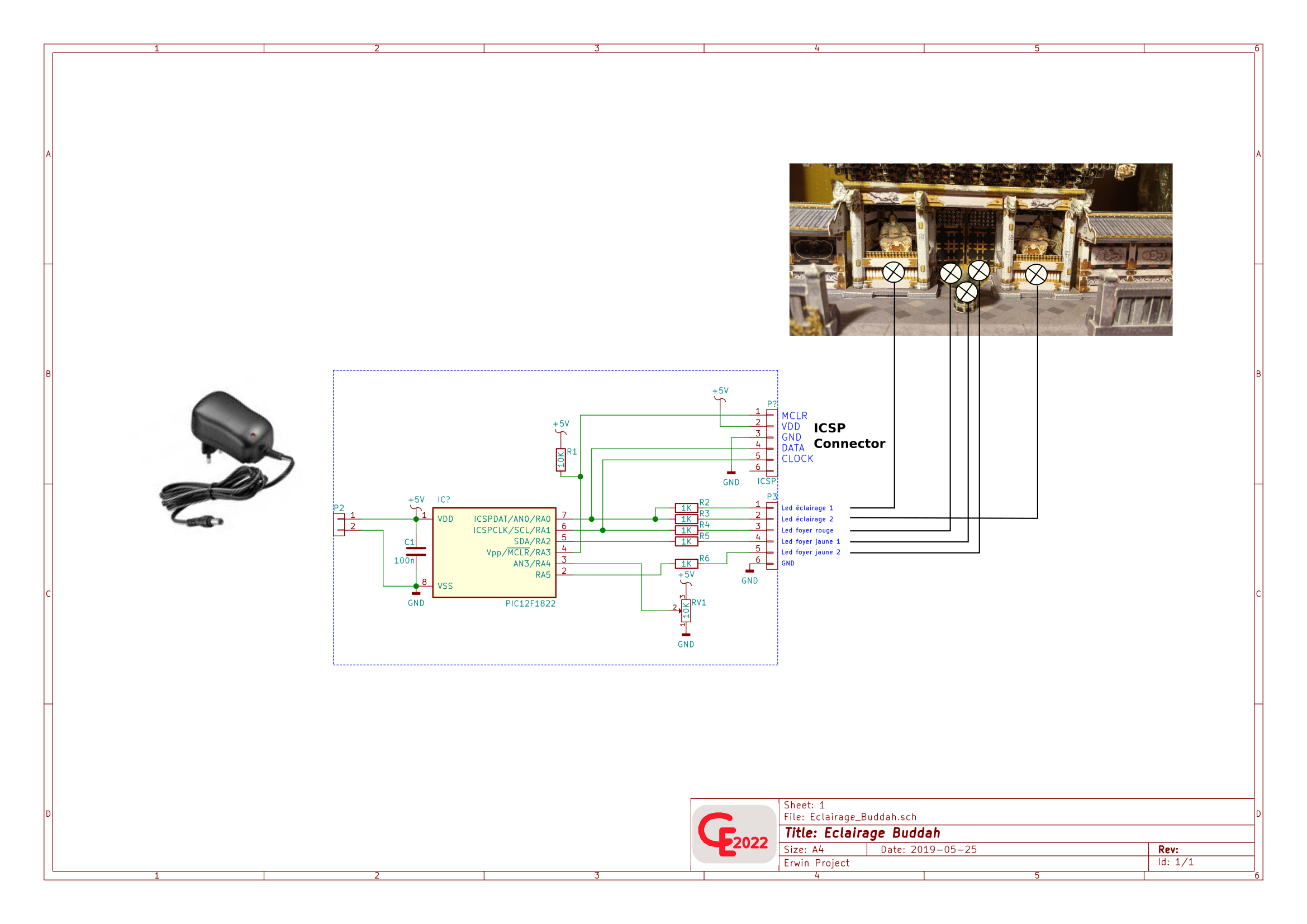
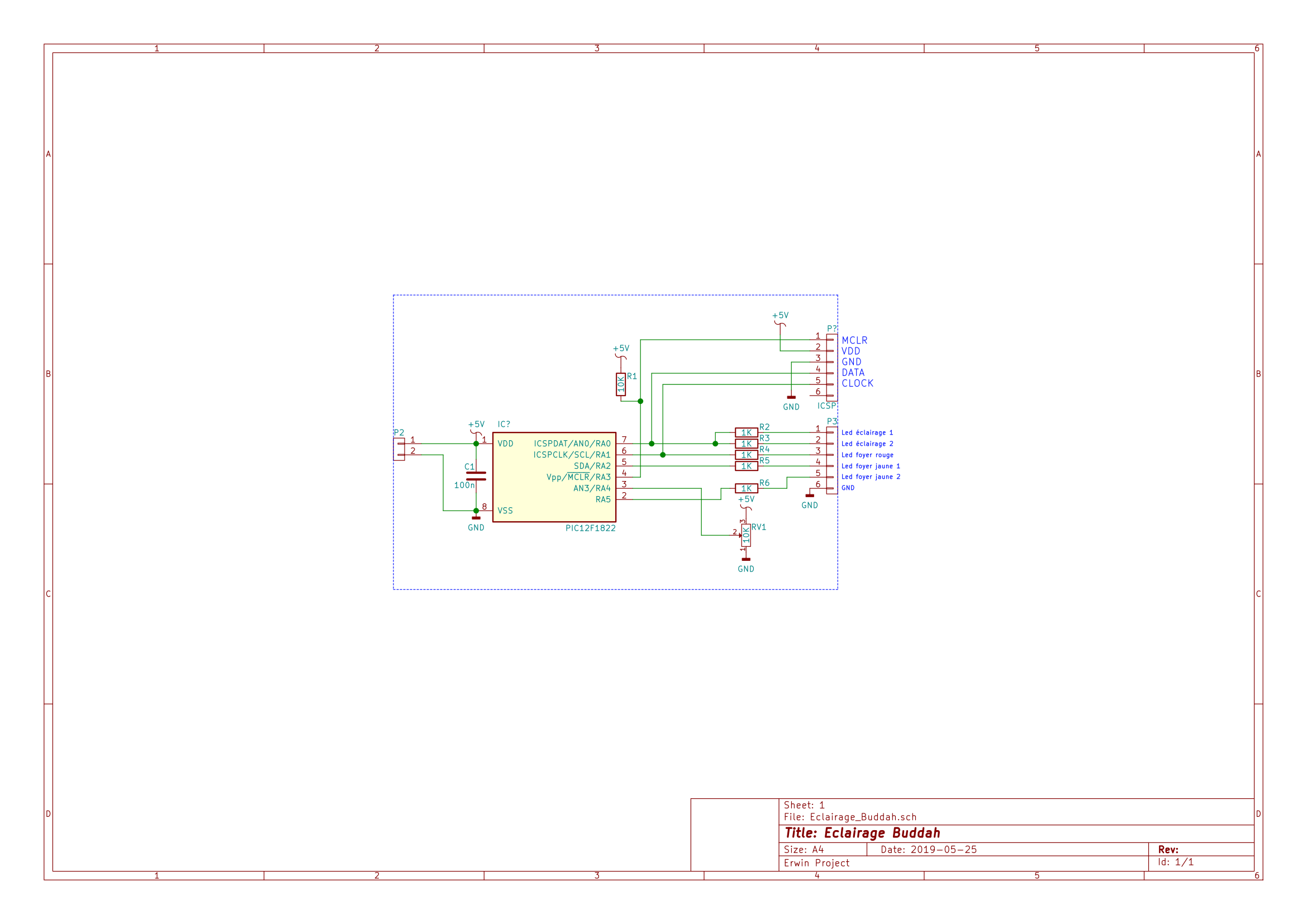
L’éclairage de la Pagode est assuré par un microcontrôleur du type PIC 12F1822(40).
Deux led’s placée dans les alcôves illuminent les Buddah, leur intensité peut être réglée à l’aide d’un petit potentiomètre.
Le microcontrôleur gère également l’effet »feu » au moyen de trois led’s, deux jaunes et un rouge.
L’effet est obtenu par un algorithme qui produit des différences d’intensités (par PWM).
Vous trouverez le programme C ici.
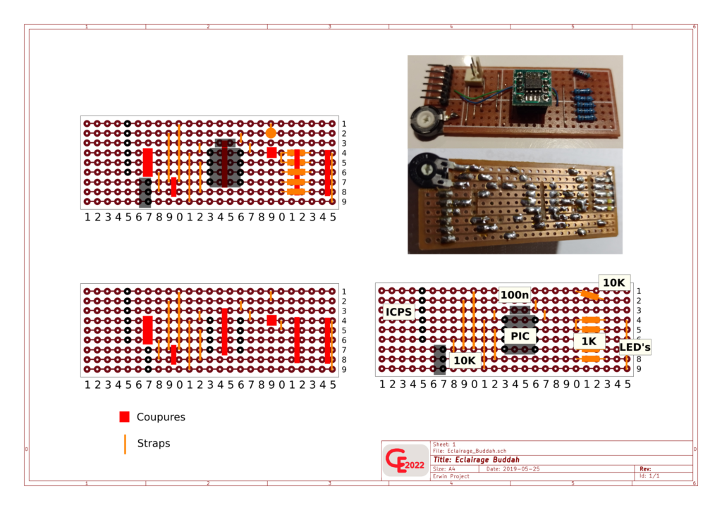
Le contrôle pourrait être fait à partir de n’importe quel µP, tel que l’Arduino, mais le choix a été fait en fonction de la place, en effet toute l’électronique tient sur une plaque à peine plus grande qu’un Arduino Nano.
Un exemple de carte « breadboard » est joint à la documentation.
Une simple alim 5V, du style chargeur USB, suffit à alimenter le tout.Les plus belles maquettes en papier; pagode Japonaise; japanese Pagoda; tie fighter, electronics led,command led; pic
Schema de Principe :
Le Schema :
Le Circuit imprimé :
Video’s :
Le Programme :
/*
* File: Feu_camp.c
* Author: Erwin
*
* Created on 20 mai 2019
*
*/
// PIC12F1822 Configuration Bit Settings
// ‘C’ source line config statements
// CONFIG1
#pragma config FOSC = INTOSC // Oscillator Selection
#pragma config WDTE = OFF // Watchdog Timer Enable
#pragma config PWRTE = OFF // Power-up Timer Enable
#pragma config MCLRE = OFF // MCLR Pin Function Select
#pragma config CP = OFF // Flash Program Memory Code Protection
#pragma config CPD = OFF // Data Memory Code Protection
#pragma config BOREN = ON // Brown-out Reset Enable
#pragma config CLKOUTEN = OFF // Clock Out Enable
#pragma config IESO = OFF // Internal/External Switchover
#pragma config FCMEN = ON // Fail-Safe Clock Monitor Enable
// CONFIG2
#pragma config WRT = OFF // Flash Memory Self-Write Protection
#pragma config PLLEN = ON // PLL Enable
#pragma config STVREN = ON // Stack Overflow/Underflow Reset Enable
#pragma config BORV = LO // Brown-out Reset Voltage Selection
#pragma config LVP = OFF // Low-Voltage Programming Disable
// #pragma config statements should precede project file includes.
// Use project enums instead of #define for ON and OFF.
#include <xc.h>
#include <stdio.h>
#include <stdlib.h>
#include <pic12F1840.h>
#define _XTAL_FREQ 32000000
//++++++++++++++++ Port output definitions
#define Led_red LATA1
#define Led_orange LATA2
#define Led_yellow LATA5
#define Led LATA0
//++++++++++++++++ Led variables
int Led_period = 270;
int Led_counter = 0;
char Led_duty = 150;
int temp_led = 0;
int Led_red_counter = 0;
char Led_red_duty = 0;
char temp_red;
char work_r = 0;
char time_pause_r = 1;
int Led_orange_counter = 0;
char Led_orange_duty = 0;
char temp_orange;
char work_o = 0;
char time_pause_o = 1;
int Led_yellow_counter = 0;
char Led_yellow_duty = 0;
char temp_yellow;
char work_y = 0;
char time_pause_y = 1;
char y,o,r = 0; //Duty random values
char a,b,c = 0; //Speed regulator counter
char z = 0; //Random delay counter
__bit sens_r; //0 = lightning up, 1 = lightning down
__bit pause_r; //speed of lightning
__bit sens_o;
__bit pause_o;
__bit sens_y;
__bit pause_y;
void init()
{
OSCCON = 0b11110000; //int osc = 8Mhz (+PLL on = 32Mhz)
ANSELA = 0b00001000; //AN3 on for pot
TRISA = 0b00011000; //AN3 = input
PORTA = 0x00;
ADCON0 = 0b00001100; //AN3 Selected
ADCON1 = 0b11000000; //Fosc/4, Vref = VDD
T2CON = 0b00000000; //TMR2 prescaler = 1:1, postscaler = 1:1
PR2 = 80; //32Mhz/4 = 125ns * 80 = 10uS (time base)
TMR2IE = 1; //TMR2 INT ON
PEIE = 1;
GIE = 1;
}
void main()
{
init();
temp_red = 200;
temp_orange = 180;
temp_yellow = 150;
TMR2ON = 1;
while(1)
{
//++++++++++ Calculate duty random values
y++;
if(y == 200) //Max illumination for Yellow led
{
y = 1;
}
o++;
if(o == 180)
{
o = 1;
}
r++;
if(r == 150)
{
r = 20;
}
for(z=0;z<(rand()%250);z++) //Random delay
{
__delay_us(330);
}
//+++++++++++ Get value of pot for Led illumination
ADON = 1;
__delay_ms(1);
GO_nDONE = 1;
while(GO_nDONE);
temp_led = ADRESH << 8;
temp_led = temp_led | ADRESL;
Led_duty = temp_led >> 2;
ADON = 0;
}
}
void __interrupt() ISR (void)
{
if(TMR2IF == 1)
{
PR2 = 80;
Led_counter++;
if(Led_counter >= Led_duty) //***********
{ // *
Led = 0; // *
} // ***************
if(Led_counter >= Led_period) //-Led_duty-
{ //variable (AN3 value)
Led = 1; //——–Led_period——-
Led_counter = 0; //fix for all leds
}
if(work_r == 0)
{
if(Led_red_duty == temp_red) //wait for full illumination
{ //to reverse way
sens_r = 1;
}
if(sens_r == 0) //lightning up
{
Led_red_duty++;
work_r = 1;
}
else if(sens_r == 1) //lightning down
{
Led_red_duty–;
work_r = 1;
if(Led_red_duty < 20)
{
Led_red_duty = 20; //Reset all
Led_red_counter = 0;
sens_r = 0;
temp_red = r; //New random duty value
time_pause_r = (r/100)+1; //New random speed value
}
}
}
if(work_o == 0)
{
if(Led_orange_duty == temp_orange)
{
sens_o = 1;
}
if(sens_o == 0)
{
Led_orange_duty++;
work_o = 1;
}
else if(sens_o == 1)
{
Led_orange_duty–;
work_o = 1;
if(Led_orange_duty < 1)
{
Led_orange_duty = 0;
Led_orange_counter = 0;
sens_o = 0;
temp_orange = o;
time_pause_o = (o/100)+1;
if(time_pause_o > 3)
{
time_pause_o = 2;
}
}
}
}
if(work_y == 0)
{
if(Led_yellow_duty == temp_yellow)
{
sens_y = 1;
}
if(sens_y == 0)
{
Led_yellow_duty++;
work_y = 1;
}
else if(sens_y == 1)
{
Led_yellow_duty–;
work_y = 1;
if(Led_yellow_duty < 1)
{
Led_yellow_duty = 0;
Led_yellow_counter = 0;
sens_y = 0;
temp_yellow = y;
time_pause_y = (y/100)+1;
if(time_pause_y > 3)
{
time_pause_y = 2;
}
}
}
}
if(work_r == 1)
{
Led_red_counter++;
if(Led_red_counter == Led_red_duty)
{
Led_red = 0;
}
if(Led_red_counter == Led_period)
{
Led_red_counter = 0;
Led_red = 1;
a++; //**
if(a == time_pause_r) //**
{ //**
work_r = 0; //** Speed regulator
a = 0; //**
} //**
}
}
if(work_o == 1)
{
Led_orange_counter++;
if(Led_orange_counter == Led_orange_duty)
{
Led_orange = 0;
}
if(Led_orange_counter == Led_period)
{
Led_orange_counter = 0;
Led_orange = 1;
b++;
if(b == time_pause_o)
{
work_o = 0;
b = 0;
}
}
}
if(work_y == 1)
{
Led_yellow_counter++;
if(Led_yellow_counter == Led_yellow_duty)
{
Led_yellow = 0;
}
if(Led_yellow_counter == Led_period)
{
Led_yellow_counter = 0;
Led_yellow = 1;
c++;
if(c == time_pause_y)
{
work_y = 0;
c = 0;
}
}
}
TMR2IF = 0;
}